
|
|
|
Volume Three - A Deep Dive Into EMF (Its Theory And How We Detect It) If you have questions about EMF and paranormal investigating and want to dig deep into the subject, this article is for you. It is quite lengthy, but digs deep into EMF and how it relates to paranormal studies. It will delve into the use of various Electromagnetic Field detection devices. It will explain what an EM field is, how it is detected, and proper methods needed to observe its effects. Along with that it will look at many false beliefs some have regarding how such fields interact with what we consider paranormal. By the time you finish reading this, you will have been exposed to enough information to make an intelligent decision with regards to the use of EMF devices in your own investigating practices. A Background On EM Fields The first step in understanding how an EM Field operates is to know what it is, how it originates, and what effects it can create. An Electromagnetic Field is defined as
The relationship was demonstrated in the 19th century by English scientist Michael Faraday. He proved that an electric current flowing through a conductor created a magnetic field around it. The properties of the field are well established. French physicist Andre Marie Ampere defined it using the Right Hand Grip Rule as seen in the drawing here.  It must also be noted that a steady DC current produces only an electric field. Such a field is not coupled to another conductor unless the conductor is in motion. This is important if one is monitoring EM Fields since a conventional EMF meter will not detect a steady state electric field. For this reason I have considered two types of EMF monitors in this discussion. The static field monitor detects steady state, unchanging fields; the dynamic field monitor will detect fields generated by alternating (changing) current sources. Another consideration of an EM Field is its strength. The Inverse Square Law of physics applies here. If we assume a field is being generated at a fixed point in space, the strength of the field will decrease as the distance between the source and the point of measurement is increased. This decrease is not random; Rather it follows the Inverse Square Law which states that "a given physical quantity (such as illumination) varies with the distance from the source inversely as the square of the distance." (Merriam Webster) In the case of your EMF Meter this factor determines the intensity shown on the meter or in the case of some meters, the number or color of LEDs illuminated. We'll get into this again later in this document. A final important characteristic is frequency. It is defined as the number of cycles, or changes, an alternating current makes over a given period of time. Usually the time frame is a 1 second interval and is measured in Hertz. In other words a 60 Hz current changes direction 60 times per second. This is the common power line frequency in the U.S. and probably the most common source of EMF encountered on an investigation. (For readers in some countries the frequency is 50 Hz.) EMF also includes higher audio and radio frequencies. These can cover the audio spectrum and extend from Hertz to kilohertz and megahertz regions of the spectrum. The frequency is also related to wavelength. They are inversely proportional to each other, as frequency increases the wavelength decreases. 
A Chart of the Electromagnetic Spectrum. The EMF meter or monitor you use on your investigations should cover all the characteristics mentioned here. Some prefer to actually measure the strength of the field, however this can be problematic as we will see later in this discussion. Another method is to simply monitor for the frequencies present. This too has its limitations and will be covered in a later section. For now we can go on to see how all this applies to conducting paranormal investigations.
The Use Of An EMF Meter On An Investigation As the chart above shows us, the EM Spectrum is quite broad. Common EMF Meters detect various wavelengths up to the lower microwave regions. Above that no common EMF Meter is available. These waves are detected using various specialty devices. Even cameras are a form of EMF detector; they detect visible light! Geiger counters can detect radioactivity so they too are a form of EMF detector. Let's look at how such EMF might be generated. Above we saw how the current flow through a conductor creates a magnetic field. If the current flow is alternating, the field reverses at the same rate as the frequency. It is this alternating field that is responsible for the reading on a dynamic EMF Meter. As the frequency increases, the range of the meter comes into play. Common EMF meters extend from Steady State up to the lower microwave regions. But notice how the wavelength continues to decrease as frequency increases. Certainly a piece of wire can create the lower frequencies and radiate them into space much like an antenna. But notice the next regions are millimeter waves. This means the "piece of wire" is a matter of only a millimeter or less in length! Such a scenario as a wire that short is possible but impractical. As we go still higher in frequency clearly we need a different explanation. At these levels EMF is generated by atomic action. We get into the area of quantum mechanics which is outside the scope of this discussion. What or how spirits may operate in these regions is still open to conjecture. This region requires additional experimentation and research so I leave it open to any who want to conduct work here. For the sake of this discussion we will limit ourselves to the common EMF Meters and Monitors we are all familiar with. Next let's clear the air on one important fallacy some have regarding EMF Meters.
The source of such beliefs goes back to Hollywood. We have seen Sam and Dean Winchester chasing spirits, demons, and other such entities through dark rooms. They often carried such devices with beeping sounds and blinking lights going off in the presence of such creatures. Good show, but not the way a real investigation is done! Why is this such a common misconception? Probably because to those who believe in it, it appears to work. So while we're digging into EMF, let's look more closely at it. The common way this method is done is to ask Yes / No Questions. You say "Blink the light once for Yes" Often there is no option for a negative response. You ask your KII meter if there is anyone here who would like to talk to us. (Most frequent question asked, by the way.) Sometimes nothing happens so the user just goes on thinking there must not be anyone here. But sometimes the meter blinks and right away the user assumes someone is present. What are overlooked are all the blinks that sometimes just randomly occur. After all, nobody asked anything so those responses are just ignored. The facts are that EMF disturbances are all around us and at times a meter will pick them up. Consider the sequence of events in the following scenario:
Why are you ignoring the extreme delay between question and response? What about those blinks when you didn't ask a question? And what about the meter just going off on its own? It almost seems like a random act.... Consider for a minute all the things that can disturb an EM Field or create one. And none are paranormal. The first problem is you are using a KII Meter which is a single axis meter. This is prone to any shift in the orientation of an EM Field. And if you are like most people doing this, you are carrying your meter around and constantly changing its relative position to the environment. And most likely there are power lines nearby. Are you familiar with Ground Loops? Also note, when I say nearby I am not limiting that to your immediate location. Power lines can induce ground loops over a distance that might reach a few miles. So what exactly is a Ground Loop and how does it cause an EM Field? 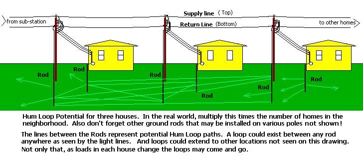 This is a simplified schematic of a single power distribution line. In reality they often are three phase, multiple circuits with varying loads being added and taken off line constantly. In the single circuit seen here one side of the line is supplying power, the other is the return wire. It is common to ground the return several places along the circuit. Usually any point where a transformer is installed a ground rod is also driven in. Your house also has ground rods at the service entrance. All of these are at ground potential, in theory. But in the real world slight differences exist between each. Though the current should flow back through the return line, a small amount also flows between each ground location through the earth. This is represented by the light blue lines between the ground points in the drawing above. And if some of this current happens to be flowing near your location, it also creates a small EM Field. Any change in the load anywhere along this circuit also changes the location and intensity of the current flowing along the return path. This in turn alters the EM Field. And if the change occurs miles away just as you ask your question, the EMF meter will respond to it. Your belief convinces you the spirits are talking! And to make matters even worse, in a common three phase power distribution system changes between loading on each phase also creates changes in its associated return loop, so there is even more possibility for disturbances in the ground loop. It doesn't end there either. Another problem that can cause random changes in the EM Field is atmospheric propagation. Short wave radio broadcasts rely on this to be heard. Since radio waves generally travel in a straight line it is how we hear broadcasts originating around the world. The signal goes up to the ionosphere and is reflected back down to earth. Sometimes they even do this multiple times, traveling up then back until they circle the globe. But the ionosphere is not constant; it varies as solar activity strikes it. Different RF Frequencies react differently at different times of day. Anyone who has ever listened to shortwave broadcasts is well aware of this. Stations can blast in like a local station and a few minutes later they will have faded away to the point they cannot even be received, only to return again later. If you look at the EM Spectrum chart above, you can see that shortwave radio is also a part of that spectrum, and your EMF meter is designed to detect such fields. So if one of these just happens to fall in your area when you are doing your communication session, the results are obvious. You have an EM Field that comes and goes; the lights blink then quit. Isn't that exactly the pattern seen in the "communication" example above? Yet with all these potential sources of contamination, some still believe their KII meter can be used as a spirit communication device. Let's be clear, EMF Meters do have a place on an investigation. A good meter or monitor can isolate potential problems that may otherwise cause false positives. EM Fields are generally not your friend if you are trying to take readings of any kind. They can interfere with other electronic devices and cause false positives. They can activate other devices at times. In other words they should be avoided whenever possible except in certain controlled experiments you may wish to conduct. The best way to do this is to identify sources of electromagnetic interference before doing any real evidence gathering. That way you can take steps to avoid areas that could be problematic. The EMF Meter can help you accomplish this pre-investigation process. A second function of the EMF meter is to monitor the area in question for changes in the background EM Field. These changes can originate from several sources. Each has a different origin and detection requires different meter configurations. Monitoring should take place anytime a session is in progress. These sessions may be EVP / AVP, video recording, and any other experiment where the background is being tested. The first consideration is background magnetic fields. These tend to drift over time due to changes in the earth's magnetic field and how it is affected by solar activity. Since these changes are generally slow, and may take hours or days to take place they are considered static fields. When it comes to EMF meters these are sometimes referred to as electric fields. Many typical EMF meters do not have the ability to detect these stable fields, however some do offer this feature. The Static Field Monitor is designed for this application.  The second consideration is more typical of the standard EMF meter. These are EM Fields that change rapidly. Power lines are a typical source for such fields. Normally you would do a scan of the area in question to isolate various "hot spots" for EMF prior to starting your investigation. Assuming you have taken steps to avoid such points of high EMF activity, you set up your equipment to do a session. The problem is that power line disturbances may change if the loads on nearby power lines change. If this happens your session may be corrupted by stray EMF. Leaving an EMF meter running in conjunction with your session will alert you in event such disturbances occur. You can then log such a disturbance and consider that when you evaluate your session. In other words, if a spike occurs on the EMF meter at the same time as noise on your recorder, there is a very good chance the noise is a result of the EMF spike. While this may not be definitive, it certainly will alert you to the possibility and you can take additional steps to validate your results by ruling out the EM Fields as a source. Another source of interference may be radio signals. If a radio transmitter is keyed up nearby it may create interference to your session. The EMF meter can indicate this signal and warn you of potential false positives. Most common EMF Meters will accomplish this type of monitoring. Radio signals may be unmodulated or modulated. Unmodulated they will not generally be as much of a problem and will simply show an indication of an EM Field. But add modulation and additional issues arise. Modulated signals may contain a voice or other audible component. This can easily be coupled into electrical equipment. Once there, for example, it can appear as a "voice" on a poorly shielded audio recorder. It will seem as though you just captured an EVP when in fact it was just radio interference. Your EMF meter can alert you to this possibility when the radio signal causes it to alarm.  This is also the primary advantage of an EMF Monitor instead of a meter. If the monitor is equipped with an RF sensor it will act as a wide band radio receiver capable of hearing multiple stations at one time. If a strong audio signal is received you can hear it in real time and use that information to rule out the false positive captured on your EVP recorder. Now that you have been introduced to a few various types of EMF meters and monitors the question arises, Which is the best? The answer to that depends on your application. Each type has certain advantages and disadvantages for each type of field. One more item that disturbs EM Fields is the cell phone. These continuously ping local towers and as such create EM Fields. For this reason cell phones should never be present on an investigation. No apps Allowed! They are also a source of local EMF even when in Airplane Mode! Leave them home or turned completely off while the investigation is in progress.
Choosing Your EMF Meter or Monitor Now that you have determined how to use the EMF Meter and where it should be applied to your application, we will explore how these devices actually work. This is where the scientific instruments are separated from the toys. We'll look at how they function and how they interact with the field. Sensors The most important part of any EMF Detection is its sensor. First we'll look at the single axis sensor. This is the basis of most cheap EMF Meters like the KII. In many versions an alternating magnetic field interacts with a coil of wire wound over a permeable core. This creates a voltage which is amplified and displayed on a meter or series of LEDs. The stronger the field, the higher the output and the higher the reading. The major problem with this type of meter is a single inductive sensor is not linear. That means that the orientation of the sensor with respect to the field makes a major difference in how well it picks up a field. As seen in the drawing presented here a field of a given intensity can be well received in one direction and can disappear in another. This makes it difficult to establish a definitive value for signal strength. One may use the method of positioning the meter in an orientation where the maximum reading is observed to work around this problem. 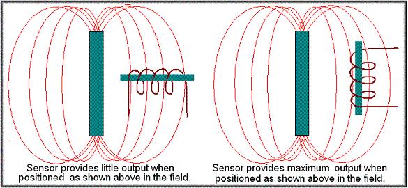 The drawing above illustrates another problem not so easily alleviated. If we are using the single axis meter for monitoring purposes we cannot be certain of the direction or orientation of any offending field. It is possible an interfering field may come from a direction where it is nulled out on the meter. Thus its presence may be missed. Some try to work around this by taking three readings at all locations in the X, Y, and Z axis. The problem doing that is you can still only take one reading at a time and has been pointed out, the EM Field is changing constantly. It can change while you are changing your meter orientation and you may get erroneous readings. The next step up is to the tri-axial sensor. This is similar to the single axis sensor except that instead of a single inductive sensor there are three of them. They are oriented along the X, Y, and Z axis. Their outputs are algebraically added together. This means that as any one sensor is oriented in a manner it becomes less sensitive, the others begin to come into a position where they offset the loss. In the end the sensor becomes non-directional. This solves the orientation issue found with the single axis meter. You obtain the actual EMF value regardless of the sensor position Another consideration is the frequency the meter covers. Most inductive sensors range from 40 Hz to 200 kHz. (ELF Range) This range covers most power sources of EMF, but does not extend very far into the RF spectrum. Some meters have incorporated multiple sensors to extend their operation well into the RF region. These also may be single or tri-axial. You will need to consult the specification sheets on your particular meter to determine its useful operating range.  While the above does explain the basic low cost EMF Meter, a problem becomes evident when we consider the low frequency limits. Most of these meters have limitations when the frequency drops below about 40 Hz. Thus the standard EMF meter does not do well with static magnetic fields such as the earth's natural magnetic field. A different means of sensing these fields is required. I should note that a few better quality EMF meters do include circuitry to measure static (electric) fields as well as dynamic. You will need to consult the spec sheet on your particular meter to determine its capability across various ranges. The fluxgate is the most sensitive method available, however this type of sensor is more expensive. The fluxgate based meter uses two coils wound over a split core. This is periodically saturated and the effects of the magnetic field alters their characteristics. A sense coil is wound over the drive coils as seen here. 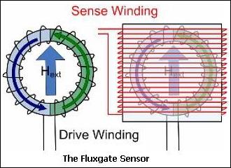 When the saturated magnetic field drops off, if no external magnetic field is present, each side of the core will both saturate and come out of saturation at the same time. However in the presence of a magnetic field they will decay at a different rate. The half operating in same direction as the drive field will come out of saturation slower than the side operating opposite direction During the time the fields are unequal there is a change in the flux of the sense winding. Faraday's Law states that when this difference exists a voltage will be induced in the sense winding. The amplitude and phase of these voltage spikes is related to the strength of the external magnetic field. The frequency response of the meter shown here is from steady state (DC) up to 400 Hz. This covers the region of the spectrum below what the standard EMF meter is capable of working with. It should also be pointed out this uses a single axis sensor. Since it is normally used to detect a steady state field such as the natural field of the earth, it may be oriented to give its baseline reading along the earth's polar field. The main purpose here is to detect changes in this field intensity so once oriented properly no more movement will occur. Only levels in field strength will be displayed.  Another less expensive method using the Hall Effect is available for detecting static fields. The Hall Effect sensor is also a single axis detector. Like the fluxgate it is oriented along the earth's magnetic field. In its basic form a Hall Effect sensor consists of a semiconductor plate as seen below. A well regulated electric current is passed between points A and B through the plate. The current flow is equal across the plate, and the voltage difference between points C and D is zero. However in the presence of a magnetic field through the plate, the electrons and hole charges in the semiconductor are pushed to opposite sides of the plate. This is due to their opposite charge potential. The direction of the push is determined by the polarity of the magnetic field.  Since the charge potential is unequal across the plate a voltage is developed between points C and D. The polarity of this voltage is determined by the electron charge potential at each point. This voltage is amplified by the meter and can be displayed or sound an alarm if it reaches a preset point. Hall Effect sensors are capable of detecting a steady state magnetic field as well as low frequency EM Fields. They are usually limited to less than 400 Hz and the sensitivity of a Hall Effect sensor is not as great as the fluxgate, but they are quite capable of monitoring the earth's natural magnetic field. Also since no complex drive circuit is needed they are much less complex than the Fluxgate which keeps the Hall cost lower. Also capable of detecting steady state magnetic fields, I would be lax if I didn't mention the cheapest, most basic method available, the common magnetic compass. While we think of them simply as a directional indicator, they will react to very low frequency EMF under 8 -10 Hz. However they also require constant observation so are not really popular as static field monitors.  One more single axis sensor needs mentioned here. This is the Inductive Sensor used as a Dynamic Field Monitor. It is unique in that it is intended to be hand held and used as a portable scanning device. The intensity of the field is not critical here since the scan is being fed to an amplifier directly and the output is sent to headphones. This allows the user to actually hear the EM Field in real time rather than measure its intensity. It is more useful as a tool for doing a preliminary investigation than actually during a session. The advantage to hearing the field is that with a bit of practice the user can learn to identify the source of the EM Field by its sound. For instance, a power line source such as a transformer or electrical conductor will generate a steady 60 Hz hum (50 Hz in some countries) as the sensor is brought near it. You can immediately identify it by that sound. If the source is ionizing radiation such as a florescent light, the frequency may still be the same as the power line, but it will be more raspy or harsh. TVs, computers, or electronics with switch mode power supplies may generate a high pitch whistle at several kiloHertz, and audio frequency EMF may be heard directly using the inductive sensor. An inductive sensor may also be modified by including a diode in series with it, and a small value capacitor across the output. This converts it to an RF sensor. As such it operates as a wide band radio receiver capable of tuning a wide range of radio frequencies. The diode serves as a detector which will demodulate an amplitude modulated signal across its bandwidth. Thus the user can hear any offending radio transmissions that might occur in the area. This is very helpful in event EVP or AVP are captured. A comparison can be made to rule out whether the radio transmission was responsible for the capture. Finally mention should be made of multiple use EMF meters. Some EMF meters cover a wide range of frequencies such as the Tri-field meter by Alphalabs. They have a selector switch that lets you choose the range of coverage. They also use different sensors for each range to get around sensor limitations In reality if you opened it up and looked at the circuitry you would see it is really two or more EMF meters in one package. The switch simply allows you to choose which one covers the band you want. This is fine, just remember you usually cannot monitor all of them at the same time.
Actual EMF Monitors and Meters Their Use We'll begin by addressing a trend to combine multiple functions in one instrument. The MEL meter is a good example of this. This is not a good idea. While it may be fine to select a range on a single EMF meter, combining operations such as a thermometer and EMF meter in one requires you to disturb your EMF meter while making the transition to the thermometer function. This disturbance can cause false EMF readings. And since temperature is not usually related to EMF there is a good possibility you may want to do a temperature reading while a session is in progress. Combining functions opens the door to false positives anytime you need to adjust or change the settings on the meter. That holds true for any combination device. It is always best to use a separate instrument for each function you want to perform during an investigation. Now let's look at the meters themselves and try to determine which is suitable for your investigating. Since these are the most common, consider the single axis meter such as the KII, the basic ELF Meter, MEL Meter, and GQ meter. Numerous other inexpensive meters also fit this category. As single axis meters they are more difficult to use due to their requiring multiple readings to be taken in each position, X, Y, and Z axis. This opens the possibility of missed or incorrect readings. Manufacturers are aware of this and most actually caution against relying on a single reading. The following is a direct quote from the operating instructions for the KII meter: 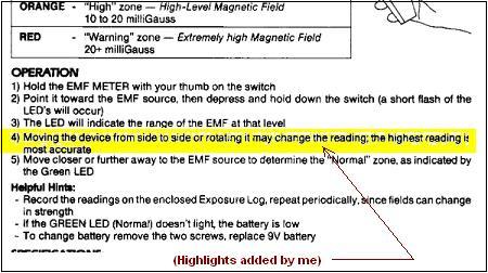 And an excerpt from the instructions for the MEL Meter indicates it too relies on a single axis:
Finally this graphic from the Gauss ELF Meter showing correct and incorrect field measurement methods: 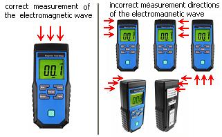 Two state you should take multiple readings and use the highest one since the highest is the one best oriented to the orientation of the field in question. The third simply says, "Incorrect" with regards to orientation. In any event all three agree false measurements can result using a single axis meter in the wrong orientation. The problem with any single axis meter when it is used as a monitoring device you never know which direction the field may originate from. It's possible, depending on its source, you could miss one entirely if it comes from the wrong direction. For this reason, I do not recommend ANY single axis meter for monitoring while investigating. They may OK for simply doing a pre-investigation, but why limit yourself to a single use? Now let's consider the strength of the field. We will assume you are using a tri-axial meter and orientation is not a factor. Your meter measures 200 milligauss. How strong is the field? The truth is you still don't know. The reason for the ambiguity goes back to what we covered in the first section; The Inverse Square Law comes into play with the reading. Remember, Meters measure the strength of the field they encounter, not the strength of the field at its origin. This is another reason for using a tri-axial sensor. The distance from the source and strength determines the strength of a given field measurement. But with a single axis meter the orientation also comes into play. Adding a second variable multiplies the chance of error coming into play. With a tri-axial sensor while we still have to deal with the distance from the source to determine its strength, it can be done much easier with the single variable of distance. As was mentioned earlier, another use for the meter is the preliminary scan for EMF hotspots prior to starting the investigation. A single axis meter may work out for that since the strength of the field is not really a concern; you are simply searching for potential problem areas to avoid. As such you are carrying your meter around and constantly changing its position. You will likely locate any EM Field as you move about. This can be accomplished using just about any meter whether single or tri-axial sensing is employed. The preliminary scan is also a good place to consider the Dynamic EMF monitor. As was mentioned this allows you to hear the EMF audibly as the inductive sensor encounters it. In addition you can learn the type of EMF it produces whether power line, audible source, or some other electronic device. As with the conventional meter knowing this allows you to take steps to avoid interference to other devices. By now you are probably asking yourself, What is the best meter or device to use for communication with the spirit world? The answer to that was covered at the start of this article. Since no evidence exists that any spirit interacts or creates an EM Field, the answer is NONE OF THE ABOVE! Not only that, but as we see here numerous sources of EMF exist. That is why we use such a wide variety of methods to monitor or locate them. With all this potential interference around us, why would we think that just because a device responds to something that a spirit did it? If we want to assume spirits want to communicate, it would make more sense to find a method that was not so prone to false positives to do so. While not really a form of communication, one area does need mentioned here. Earlier I stated spirits do not affect magnetic fields and that is true. But since the paranormal extends into other things besides just ghosts and spirits, some cases have surfaced where claims have been made where UFOs have interacted with electronics. For this reason there may be something to be said for using an EMF monitor to alert you to the presence of UFO activity. It may not be conclusive, but it can't be ruled out completely either. We have covered numerous areas of EMF detection and multiple methods of investigation in this article. Some may fit with your investigation methods; some may not be something you normally do. While there is no "one size fits all" type of investigation, and even conditions may change between individual cases you are working, some may wonder what methods and equipment I use on a typical investigation. I'll wrap this up with a brief overview of a typical investigation, concentrating on how I deal with EMF. 1) - The first step is to interview the witness to find out where the issue in question is concentrated. (It seems pointless to investigate the second floor if the case is in the basement!) 2) - Once the location is determined, I do a pre-investigation scan to isolate any hot spots to avoid. For this I use an Alphalabs tri-axial meter 100XE. (Note, this is an older obsolete model and has been updated by the TF-2.) I do a scan of the area I intend to investigate and locate any hot spots. Next I go back using a dynamic EMF monitor to determine the nature of the EM Field present. The monitor is a custom built high gain amplifier with detachable inductive sensor wand. 3) - The EMF Monitor probe is then switched out with one intended for RF monitoring and the system is placed in a central point of the area under investigation. If I am doing an EVP session I often feed the output of this device into one channel of the audio recorder. There it provides a reference should any radio source be detected. It will be saved on the EVP audio recording for comparison. 4) - Finally I set up a Static Field monitor in the area. This device uses a Hall Effect sensor to monitor the steady state background magnetic field. The background field is set and its natural level is set as a baseline. This device uses a window detector to alarm if the magnetic field drifts above or below the baseline. 5) - Once everything is in place I am ready to begin the actual investigation sessions as needed. If I am going to do another area at this location, the process is repeated starting at step 2 above. The above represents a basic outline for a standard investigation process. It may be altered at times if conditions require a change in protocol. And one more thing I use related to UFO activity. I have installed a Hall Effect Monitor and have it running constantly keeping watch for activity around my location, just in case one happens by. Several years ago I did actually pick up a disturbance and recorded its passing on a data logger. But though it tripped an alarm and I went out and looked for it, I saw nothing. Better luck next time! And there you have it. We have covered what an EM Field is, how it may impact your investigation and evidence gathering, and how to detect it so you can prevent its negative effects. This is not meant to be an all inclusive condemnation or recommendation for any particular device. There are numerous different manufacturers of many kinds of EMF devices. You will need to research any particular device on your own. But this will give you enough information to help you make an intelligent choice when you are searching for your own EMF meter. Be Skeptical, but Keep An Open Mind.
© May 2024 - J Brown |


